Table of Contents
TeleR2 / TeleR4 / S7-Firewall

TeleR²-Router PPPoE | Art.Nr. 9374-PPPOE
TeleR4-Router PPPoE | Art.Nr. 9374-4-PPPOE
S7-Firewall | Art.Nr. 9374-S7-Firewall
![]()
Introduction
The TeleR are scalable routers. Over the integrated web interface you can configure and operate the TeleR² / TELER4.
Applications for TeleR² / TELER4 are as Gateway / Connect / remote maintenance of:
- Automation networks
- ProfiNet networks
- Standard Ethernet networks.
Specifically TeleR² / TeleR4 supports Simatic S7 systems from Siemens. With few handles the TeleR² / TeleR4 is running in the desired mode.
For TeleR² / TeleR4, depending on the mode expansion modules available.
Device variants
In the standard version TeleR² is fitted with a WAN port and a LAN port and the TeleR 4 is with a WAN port and 3 LAN ports with switch fitted.
The following operating modes are possible.
| Modes | Ethernetgateway (bridge) IP-Router Following DSL / cable modem (PPPoE) |
|---|---|
| Services | DHCP Client/Server PPPoE-Client NTP Client/Server OpenVPN Client/Server (VPN@Office) DynDNS Client Firewall |
| Connections | 1 x WAN 1 / 3 x LAN-Port as Switch |
First Start
You need to configure a PC with web browser
- power supply on POW
- Connect PC and TeleR-Router via Ethernet cable
- set IP-Adresse in the IP-area of TeleR2 / TeleR4
- for WAN-side 192.168.1.x
- for LAN-side 192.168.2.x
- Call in the browser the IP address of the router
- for WAN-side 192.168.1.57
- for LAN-side 192.168.2.1
- Confirm the login window with “OK”
- Add under WEB-User a SuperUser (su)
- Depending on the application you need to make different settings
- Establish connection to TeleR
Usage
Routing between two networks
That TeleR² / TeleR4 can route between two networks, you need to make the following settings:
- configuration
- set routing mode
- Office, for routing from LAN to the routing interface
- Machine, for routing from the routing interface to the LAN
- Routing interface1): WAN/IP
- set up WAN/LAN IP-Address(es)
- User
- WEB-User
- create Superuser (su)
(prevents unwanted access)
OVPN-Server
In TeleR² / TeleR4, we have implemented the popular, released under open source OpenVPN. For detailed information, see http://www.openvpn.net. With OpenVPN we provide in TeleR² / TeleR4 a new network interface. This interface is connected via a quasi line (virtual line) with the OpenVPN interface of the partner device. The line is realized with software. Hereby all protocols for this interface, will be exchanged by its own UDP / TCP channel. One can say there is a telephone connection between the devices via UDP / TCP prepared. Of course, the connection is encrypted. The keys are stored in TeleR² / TeleR4.
Proceed as follows:
- configuration
- Routing Mode: Mashine
(Routing from Routing interface to LAN) - Routing Interface2): WAN/OVPN
- Open VPN
- OVPN-Mode: Server (UDP) or Server (TCP)
- if necessary, change the default port
- IP-Pool: IP-Address range for the OVPN-Connection
- Interface: This sets the to-reach interfaces
- optionally activate services on the interface (web interface, ping, SSH (for developers only))
- create VPN-User
OVPN-Client
In TeleR² / TeleR4, we have implemented the popular, released under open source OpenVPN. For detailed information, see http://www.openvpn.net.
TeleR² / TeleR4 can be operated as OVPN client.
When this mode is activated automatically a OVPN connection to OVPN server is established.
You can use this mode when e.g. the TeleR² / TeleR4 should not take on the WAN port routing for LAN.
Proceed as follows:
OVPN-Software for PC
On our website you will find OpenVPN Installer for Windows 32/64-bit as download.
This package is preconfigured for our TeleR² / TeleR4.
Open VPN connections can also be built from Linux or Mac operating systems.
- install Open VPN Client Software
- install configurations data
- under C:\Program Files\OpenVPN\config you can usually find the configuration
- open “TProf2config.ovpn” and insert the OVPN-Server data
- remote “Server-IP-Address”
- Port “Server Port”, default 1194
- proto udp (default) or tcp (like OVPN-Server settings)
- Start the OVPN-Client Software as Admin
- On the taskbar at the bottom right you can find the application
- Right click select desired profile
- click “Connect”
- then enter the user name and password
- while connecting all settings are set
Connect 2 TeleR
There may be two TeleR be interconnected. Here, the tunnel between the two devices is set up and all the users of
the company network can thus access the remote network.
The user can use this connection by setting the routing on the PC or the router.
Sample:
TeleR IP-Address LAN in house: 192.168.0.100
TeleR IP-Address LAN on Machine site: 192.168.3.50
IP-Address PLC: 192.168.3.10
To connect two TeleR, proceed as follows:
- set the TeleR on the machine side as an OpenVPN server
- Open VPN
- Set OVPN-Mode “Server (UDP)” or “Server (TCP)”
- Set Interface Permissions (PING, Web Interface)
- Set up VPN users
- Configuration
- set up the TeleR on the own house as an OpenVPN client
You can test the configuration by sending a ping to the network port of the target network (allow “Ping” interface must be set)
PPPoE
TeleR² / TeleR4 supports the PPPoE protocol. Set the parameters for operation on a DSL/cable modem here. For the overview and for the easier configuration, the settings for standard gateway and DNS can be done here. As a rule, this should be set to “auto from PPPoE”.
- Configuration
- Set the routing mode
- Office, for routing from the LAN to the routing interface
- Machine, for routing from the routing interface to the LAN
- Routing Interface 7): WAN/PPPoE or WAN/OVPN
- PPPoE: activate
- Enter user data from the provider
- If necessary, set the gateway e.g. to “auto from PPPoE”
Profinet-Router
TeleR² / TeleR4 can optionally be operated as a Profinet router (Profinet option).
For this, you need 2 TeleR² / TeleR4.
The Profibus connection is implemented via a secure OVPN connection.
The VPN connection can be established via WAN/IP or via WAN/PPPoE.
The router configured as an OVPN client automatically connects to the OVPN server.
Attention : No real-time data exchange is possible
To set up a ProfiNet connection with 2 x TeleR² / TeleR4, proceed as follows:
To connect two TeleR, proceed as follows:
- Set up TeleR on the machine side as an OpenVPN server
- Open VPN
- OVPN-Mode: “Server (UDP)” or “Server (TCP)”
- Set Interface Permissions (PING, Web Interface)
- Set up VPN users
- Configuration
- Routing Mode: “Machine”
- Routing interface 8) “WAN/IP” or “WAN/PPPoE”
- possibly activate DynDNS / PPPoE
- TeleR in your own house set as an OpenVPN client (Open VPN menu)
- Open VPN
- OVPN-Mode: “Client (UDP)” or “Client (TCP)”
- Enter the VPN server, user and password
- Configuration
- Routing Mode: “Office”
- Routing Interface 9): “WAN/IP” Or “WAN/PPPoE”
You can test the configuration by sending a ping to the network port of the target network (allow “Ping” must be set on the interface)
IP-Address-Changer
If you have machinery with the same IP address and want to connect them together, but the IP addresses can not be changed, use our TeleR² / TeleR4.
Example:
Shared assets IP address: 192.168.1.10
Plant 1: 192.168.3.15
Plant 2: 192.168.3.16
You only need to make the following settings for the connection:
- Routing Mode: Machine 10)
- Routing Interface 11): WAN/IP
- Adjust WAN / LAN settings
- WAN-IP first teleR: 192.168.3.20
- LAN IP: 192.168.1.20
- WAN-IP second TeleR: 192.168.3.30
- LAN IP: 192.168.1.30
- Enable IP Address Changer
- First TeleR
- New address (WAN) 192.168.3.15
- Old address (LAN) 192.168.1.10
- Second TeleR
- New address (WAN) 192.168.3.16
- Old address (LAN) 192.168.1.10
Now the machinery are reachable under the new IP addresses and can communicate with each other.
Set routing
In order to reach the plant network via the PC, there are several possibilities:
- Start the prompt / console as an administrator
- Add local routing:
route add “Destination IP” “Gateway”
e.g. route add 192.168.3.10 192.168.3.50 - Or total IP range:
route add “Target IP range” mask “Netmask” “Gateway”
e.g. route add 192.168.3.0 mask 255.255.255.0 192.168.3.50 - Route print command prints the currently set routes
- Test the routing e.g. with a ping to the destination network
- In your router / switch, enter routing to the TeleR² / TeleR4 WAN-IP
- Test the routing e.g. with a ping to the destination network
Configuration over Webinterface
 In the “configuration” main menu you will find all necessary settings,
for the operation of the TeleR² / TeleR4. The input forms are usually self-explanatory.
In the “configuration” main menu you will find all necessary settings,
for the operation of the TeleR² / TeleR4. The input forms are usually self-explanatory.
However, we are happy to accept suggestions from users to make the operation even easier.
In the delivery state, the following IP addresses are set:
WAN: 192.168.1.57
LAN: 192.168.2.1 without DHCP server
You have the following options to access via WEB Browser the TeleR² / TeleR4:
- On the PC, assign an IP address from the corresponding network segment (for example, 192.168.1.100 or 192.168.2.100) and connect the PC to LAN or WAN over Ethernet.
- Enter the browser at http://192.168.1.57 or http://192.168.2.1
Configuration

| Parameter | Possible setting | Routing direction / function |
|---|---|---|
| Device name | „at will“ | |
| ProfiNet | yes /no | Determines whether the TeleR² / TeleR4 is to be used as a ProfiNet router. set WAN/OVPN as the routing interface |
| Standard Gateway | fix (as specified) From WAN over DHCP From WAN over PPPoE from LAN via DHCP from modem via PPP | |
| 1. DNS | ||
| 2. DNS | ||
| Routing Mode | Office | From the LAN to the routing interface |
| Machine | Routing interface to the LAN | |
| Routing interface | WAN/IP | IP-Routing over WAN |
| WAN/PPPOE | IP-Routing over PPPoE on WAN-Port | |
| WAN/OVPN | only Routing over OVPN on WAN-Port |
WAN/LAN settings

The WAN/LAN port can each receive up to 3 different IP addresses and subnets.
The port can also be operated as a DHCP server or client. The necessary data for the IP assignment is entered here.
For the operation as DHCP/server, fixed assignments MAC- to IP-address can be defined (see below, “DHCP fixed addresses”).
Next, specify which services are available on the port: Web Config, Ping, SSH (for developer only)
DHCP-Server operation
DHCP-settings:
- DHCP: Server
- enter Start-IP e.g. 192.168.2.100
- enter End-IP e.g. 192.168.2.150
- enter Subnet e.g. 255.255.255.0
- Router-IP: z.B. LAN-IP 192.168.2.1
- 1.DNS: enter DNS-Server-IP
Modem
 A USB modem can be plugged into the USB interface, which makes the dial-in to the Internet.
A modem connection is implemented as a PPP connection. Thus, TeleR²/TeleR4 can also be used with other dial-up routers.
Thus, TeleR 2/TeleR4 is an ideal substitute e.g. for Teleservice IE from Siemens.
| Parameter | Possible settings | Description |
|---|---|---|
| Dial-up mode | Sound Impulse | Selection procedures for the Internet. Standard is sound, only old telephone systems require impulse |
| Substation | Yes No | Indicates whether the operation is on a PBX. If yes, the dial-up number should be stopped |
| Dial-up number | Number | Only required for telephone systems requiring dial-up to the external telephone network |
| Number of rings | 0-5 | Number of rings. Before the modem receives a call. 0 = Modem does not answer |
| Country | Select the country in which the device is operated | The modem adapts to the technical characteristics of the telephone line in the respective country. As a rule, a choice is available between Europe/Germany and the USA |
| Max. baud rate | Maximum connection speed that the modem uses | With varying line quality, it may be more effective to operate the modem at a lower speed. This saves automatic negotiation of new modulation |
| locale IP-Address | IPv4 IP-Addresses | AUTO setting, no settings required |
| Partner IP-Address | IPv4 IP-Addresses | AUTO setting, no settings required |
| Services at the interface | Web-Config Ping SSH | Services to be available at the interface |
ProfiNET-Router (Only possible with ProfiNET option)
If ProfiNet is activated, TeleR² / TelleR4</ sup> is used to connect / remote control Profibus networks. Here is a schematic example:

The ProfiNet connection is implemented via a secure VPN connection. The VPN connection can be established via WAN (TCP / IP) or via WAN / PPPoE.
To set up a ProfiNet connection with 2 x TeleR² / TeleR<sup>4:
- Activate the ProfiNet option on both devices
- Set up one page as an OpenVPN server and the other as an OpenVPN client (see below)
- Possibly. DynDNS / PPPoE
Settings configuration:
| Parameter | Possible setting | Routing direction / Purpose |
|---|---|---|
| Device name | „at will“ | |
| ProfiNet | yes | Determines whether the TeleR² / TelleR4 should be used as a ProfiNet router. Routing interface: WAN / OVPN fixed |
| Standard Gateway | - Fixed (as specified) -From WAN to DHCP - from WAN to PPPoE - from LAN to DHCP | |
| 1. DNS | ||
| 2. DNS | ||
| Routing Mode | Office | Allows routing from LAN to routing interface, router in-house router |
| Machine | Allows routing from the routing interface to the LAN, TelleR router on the PLC side | |
| Routing interface | WAN/OVPN | Routing via VPN to the WAN port |
The devices connect automatically. If the connection is successful, it can be communicated between the two ProfiNet networks.
Attention!
No real-time data exchange is possible.
Static Routes

| Parameter | Possible setting | Function |
|---|---|---|
 | delete record | |
 | edit record | |
 | save record | |
| Name | “at will” | Used e.g. as identification |
| Target | 192.168.3.1 | Target IP-Address or area, in which is to be routed |
| Adr.-Type | net | Entire IP range is routed |
| host | Only this IP address is routed | |
| Netmask | z.B. 255.255.255.0 | Netmask of the IP address or the IP range |
| Gateway | z.B. 192.168.1.1 | Gateway for Routing |
Proxy settings

| Parameter | Possible setting | Function |
|---|---|---|
| Used Proxy | yes/no | Proxy On or off |
| Address/Name | z.B. 192.168.1.253 | IP-Address or DNS of the Proxy-Servers |
| Port | z.B. 25000 | Port of the Proxy-Servers |
| Auth-Mode |  |
IP-Address-Changer

Bring same participants with the same IP address into a different network.
Enter the desired destination IP address in the left column and the known IP address in the right column.
If you set the hacker to active, this IP address is now available under the new one.
Example:
| Name | IP-Address | Change of IP-Address possible | new IP-Address |
|---|---|---|---|
| PLC 1 | 192.168.0.100 | no | 192.168.3.15 |
| PLC 2 | 192.168.0.100 | yes | 192.168.3.16 |
Configuration looks like following:

PPPOE-settings

Set the parameters for operation on a DSL/cable modem here.
For the overview and for the easier configuration, the settings for standard gateway and DNS can be set here. As a rule, this should be set to “auto from PPPoE”.
Again, you can select which services are available at the interface.
| Parameter | Possible setting | Purpose |
|---|---|---|
| PPPoE on WAN | yes/no | Determines whether PPPoE should be active on the WAN port |
| PPPoE-Servicename | optional | Will be communicated to you by your Internet service provider. Usually free |
| username | As transmitted by the provider | |
| password | As transmitted by the provider |
Phone book
| Parameter | Possible setting | Purpose |
|---|---|---|
| Name | Name of entry | at will |
| Phone number | Number of the participant | The connection is established by clicking on the number |
| Baudrate (not at ISDN) | 1200- 56kBit | Maximum connection speed with the partner |
| User | Users from the dial-up user list | User for dial-up access, is managed under dial-up users |
All systems with modem connection are managed in the telephone book. The connection is established with a partner simply by clicking on the telephone number.
User and password are maintained in the dial-up user database. It is therefore possible to use a user for several plants.
TeleR² / TeleR<up> 4 </sup> can also be used for other dial-up PPP accesses
If you still can not see the phone book, empty the cache of your browser
DynDNS Config
 If TeleR²/TeleR4 should be available via the Internet, e.g. via OpenVPN, the Internet IP address of the device must be known.
In this case it is useful not to work with a fixed IP address, since the provider may change the IP-address after a new establishing a connection (for example by PPPoE).
It is more useful here to address the device with the same domain name.
The service provider DynDNS offers a service on the Internet (http://www.dyndns.org). DynDNS = Dynamic DomainNameSever. You must log on to DynDNS to operate the service. For more information, see the DynDNS homepage. Up to 5 Dynamic IP addresses are free. If you need more than one, you can book a corresponding number of domain names at DynDNS. The price is very reasonable about 30, - US$ a year.
On the whole, this works like this:
You register the desired hostname with DynDNS. (E.g. Myplant.dynalias.com).
You will receive your user and password for your access.
Enter this data in the DynDNS Config setting and set “Use DynDNS” to Yes.
The DynDNS refreshes the data at DynDNS in the specified time interval. If the provider assigns a new IP address,
this is corrected again within this interval, thanks to DynDNS. Your TeleR² / TeleR4 can then be reached
by the registered name e.g. testgeraet.dyndns.org
You enter this domain name in your office device at the VPN participant.
| Parameter | Possible setting | Purpose |
|---|---|---|
| used DynDNS | yes/no | Enable or disable service |
| DynDNS Hostname | z.B. tesgeraet.dyndns.org | registered Hostname |
| Update-Intervall | 30 | IP-Address Adjustment in the set minute interval |
DHCP fix MAC / IP address assignment

If the built-in DHCP server (on the WAN or LAN) is operating, it can be useful to always allocate the same IP address to certain IP devices.
Here you can specify which MAC address, which IP address is assigned.
Date/Time/NTP-Client

Here you can change date and time.

In order for TeleR² / TeleR4 to always work with the current time, we have implemented an NTP client.
This allows TeleR² / TeleR4 to synchronize itself automatically over a time server, date and time available on the Internet or with another network.
| Parameter | Possible setting | Purpose |
|---|---|---|
| NTP-Client-operation | yes/no | Turns NTP client on or off |
| Servicename | IP-Address / Domain name of the NTP-Servers | Enter the IP address or domain name of the desired NTP server. Make sure that this server is reachable over the specified routing path |
| Zeitzone | Time zone in which and TeleR4 is operated | Necessary for TeleR² / TelleR4 to have the correct local time |
System button, Reset system
The configuration button can be found on the back of the unit

Under the item “System button” you have two possibilities, which is allowed when the button is pressed.
At least one option must be selected!

| allow factory settings |  | The device can be set to the delivery condition |
|---|---|---|
| Allow start by default | | The device boots with network / IP addresses of the delivery state |
Attention!
Use one of the switch ports to configure it.
Do not leave the unit in operation.
Disconnect the device from the production network and perform the reset in an autarkic environment.
The configuration computer and the device should not be connected to the corporate network.
No worries, we still have no factory reset.
Only the activated options are available.
Basic setting / Factory setting
Basic setting:
- The device boots with network / IP addresses of the delivery state (see configuration)
- Settings can be changed
- Network settings are activated after restart
Factory setting:
- All settings will be deleted
- Device starts in the delivery state
Flow:
- Office clerk or similar ready
- Make the device de-energized
- turn back on
- Power LED is lit.
- If the LED S1 lights up, press and hold down the button with the office clip until LED S1 goes out, then release the button 12)
- Press the button in the desired mode
LED S1 Blink Modes:
| Very slow flashing approx | Carry out basic adjustment |
| Very fast flashing (in 50ms clock) | Perform factory setting |
Routing Firewall rules

Normally routing is allowed to all network users. As soon as an entry in this table exists, access is only possible via the above rules. In the standard forwarding, the routing is only possible to LAN or LAN. See operating mode. The “Advanced mode” allows rules in both directions.
Open-VPN
 In TeleR² / TeleR4 we have implemented the popular OpenVPN published under Opensource. For detailed information, see http://www.openvpn.net.
Here I would briefly explain the function of the OpenVPN, as implemented in the TeleR² / TeleR4
Basically there are two operating modes of the OpenVPN: server or client.
The device is normally configured as a server on the plant (machines).
With OpenVPN, we are providing a new network interface in the TeleR² / TeleR <4> / .
This interface is connected via a line (virtual line) to the OpenVPN interface of the partner device.
The line is implemented with software. All protocols for this interface are exchanged via a separate UPD / TCP channel.
One can say it is a telephone connection between the devices by UDP / TCP manufactured.
The connection is, of course, encrypted. The keys are stored in the TeleR²/TeleR<sup>4.
Configuration of the OVPN-operation
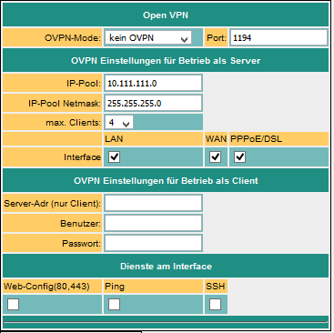
| Parameter | Possible setting | Purpose |
|---|---|---|
| OVPN-Mode | no OVPN Server (UDP) Client (UDP) Server (TCP) Client (TCP) | Sets the OVPN mode of the device. In the server operation, TeleR² / TeleR4 is waiting for a connection; in the client mode, TeleR² / TeleR4 itself takes over the connection setup to the partner |
| Port | 1024 - 65535 | Port number on which the VPN service should run, Standard 1194 |
| IP-Pool (only Server) | default: 10.111.111.0 | The IP address is assigned to the partner (client) from this pool |
| IP-Pool Netmask | default: 255.255.255.0 | Netmask for the IP pool |
| Server Address (only in Client operation) | IP-Address or Url of the Server | The address of the server. Can be in the notation xxx.xxx.xxx.xxx or in the plain text (as Url). Used only in client mode |
| User | username | Name of the user with which he authenticates himself on the server |
| Password | user password |
The options Services at the interface define which services are available with an existing VPN connection
| Service | Description |
|---|---|
| Web-Config | Enable / disable access to the web interface via port 80 or 8080 |
| Ping | Deactivate / enable response to ping requests |
| SSH | Deactivate / enable SSH-access |
Open VPN-Routing (Option)
Here, it is determined, in which form to the WAN / LAN port over VPN is routed.

off: Routing to the interface is not possible
===>: Routing from VPN to the interface
⇐==: Routing from the interface to the VPN
⇐=⇒: Routing in both directions
Access authorization
Who can now build an OpenVPN connection?
How can access be controlled?
ATTENTION: In principle, anyone with the certificate and the IP address of the TeleR can establish a VPN connection and access the device.
You can use your own certificates in the “Advanced Router” extension.
This gives you more security
VPN-User

Here you can manage users who are allowed to connect via OpenVPN.
VPN-connections

In the VPN connections, like a phone book, your machines can be managed.
The server address, the protocol, the port, and a reference to a VPN user are entered (see above).
User administration
 In the user administration, you manage the users, which are allowed to use the WEB interface.
The access data for users who are allowed to establish a dial-up connection (modem) are also maintained here.
In the user administration, you manage the users, which are allowed to use the WEB interface.
The access data for users who are allowed to establish a dial-up connection (modem) are also maintained here.
WEB-user
Here is the form for entering the WEB-Interface users. Per user, different authorizations can be assigned. In principle, only one user with “SU” changes can make changes. U1 - U5 may only operate the interface. In the TeleR² / TeleR <4> extension modules, “U1” - “U5” have more precisely specified operating rights.

User level:
SU = Super User,can use all settings
U1-5 May only display or change certain settings
DFÜ-user
Here is the form for entering the dial-up interface users. The user only gets access if active is set to “yes”. Further, the addition “Dial in & out” or only “Dial out” is available.
If a user chooses, all entries that are set to “Dial in & out” are checked. Other users do not have access. In the telephone book the assignment is made

Maintenance

Here you will find all the settings required for the maintenance of the TeleR.
New Firmware
- Unzip the downloaded file
- Disconnect the TeleR² / TeleR4 from the mains and connect it to the PC
- If necessary, set the IP address on the PC
- Call WEB interface
- Firmware Upload: Select file *.bin
- Save
- confirm with “yes”
- LED S1 flashes very quickly
- wait until LED S1 is in steady light
System status
Display of the device status. Here, e.g. with built-in VPN connection.

Network status

Displays all currently assigned IP addresses and link states of the individual ports.
You can also find the current routes.
Optional Function
HMI-Notification Module

With the HMI-Notification Module SMS and email messages (error and maintenance messages) can be, depending on the event, sent automatically to practically any number of recipients.
The system automatically assigns the messages to the respective recipients and sends the message via the correct provider.
Please note:
By sending SMS messages and e-mail messages, additional costs arise (telephone fees, charges for Internet access, etc.).
Please check with your provider for the amount of the respective fees.
For the HMI module to work properly, some basic settings must be made.
The following items must be set up:
- Pagerprovider
- Pager recipient
- Emailserver
- Email recipient
- PLC connections
- PLC variables
- Standardization (optional)
- Notifications
- Initial setting Activate the HMI option
- Activate SMS dispatch or activate email delivery
The HMI module is also secured by access protection via WEB browser. The necessary rights are indicated for the corresponding points.
Set up the email server or email account

In order for the TeleR² / TeleR4 to send an e-mail, an e-mail account or a server is required, which receives and forwards the messages.
Under Name, enter a meaningful expression for you.
The “Address” field contains the host address of the e-mail server. You can either use a local server (on the local network) or a public on the Internet. The input can be a name (for example, mail.gmx.de) or a fixed IP address.
However, ensure that the corresponding entries are set for the DNS server, gateway or routes, in order to ensure a smooth e-mail transmission.
If an email is sent, TeleR² / TeleR4 first tries to reach the appropriate server via the current options (set DNS and gateway).
If this is not the case, an Internet connection is established under the setting configuration → PPPoE / DSL or configurations view → Internet → Provider and then tries to find the server.
This connection is also used when the Internet connection is set to manual. If the connection to the Internet was established by this way,
after 2 minutes of idle (no email is present) or at least after 10 minutes the connection will be closed.
For the Internet via modem, you can use so-called Internet by Call providers.
In the “Email message buffer” menu item, you can track the status of the email and find any errors.
'Email' is the mail address the recipient sees as the sender. This address should be exists, as otherwise anti-spam filters might eliminate these messages. User and password refer to the email account.
Set up the e-mail recipients

In the next step, you specify the recipients of the e-mail messages.
| Field | Description |
|---|---|
| Name | Free selectable display name |
| Recipient's e-mail address | |
| Server | Select the desired mail server for sending to this recipient |
| G0 – G9 | Reporting groups. Each recipient can not belong to one or more message groups. Below, you can assign different message groups for each message, similar to this one. Thus, a message can be distributed easily to the relevant recipients. |
Create message
Connections are required for access to the PLC. Connections are currently supported for the SIMATIC S7 over TCP/IP.
Then configure the desired variables.
You can now specify scaling for output.
Then, you create your desired messages.
Configuring the PLC connections

| Field | Description |
|---|---|
| Name | Own name of the PLC |
| Connection | Connection type to the PLC (here TCP/IP) |
| active | Communication to the PLC |
| cycle | Specifies the time period according to which the PLC is to exchange data |
| Addr. SMS-Status | Is intended for feedback of the state of the HMI module. If you want to monitor the communication status and the SMS dispatch in the PLC, enter the address of a “word on” there. E.g. Data block or flag. TeleR² / TeleR4 then writes the maximum number of send attempts for pending messages for each communication cycle in the low-order byte. If the number exceeds 254, 254 is always used here. The background for this procedure is explained later. If the number of send attempts is > 0, the sending of a message has failed. This allows the PLC to monitor the SMS dispatch. Now it should also be monitored whether TeleR² / TeleR4 is communicating with the PLC. This can be done easily. Describe the counter byte in your PLC regularly with 0xFF. After the specified cycle time, a value other than 0xff must be set there. However, you should measure this time generously as the cycle can shift when communication problems occur with other controllers. The high-order byte is reserved for later extensions. This is currently overwritten with “0”. Example: If you are using MW 200, the MB201 is set to the counter reading, and in MB200 the value is 0 |
Configuring the variables

Now create the desired variables to be displayed or processed.
| Column | Usage | ||||
|---|---|---|---|---|---|
| Name | For free use | ||||
| Connection | Assign the variable to a PLC connection | ||||
| Address | The actual address in the PLC according to the following rules: | ||||
| data area | Data type | ||||
| Input | Output | Flag | Data blocks | ||
| E 1.0, I 1.0 | A 1.0, Q 1.0 | M10.1 | DB1.DBX 1.0 | Bit(Boolean) | |
| EB 1, IB 1 | AB 4, QB 4 | MB 20 | DB2.DBB 20 | BYTE | |
| EW 4, IW 4 | AW 6, QW 6 | MW 100 | DB4.DBW 0 | WORD | |
| ED 4, ID 4 | AD 6, QD 6 | MD 100 | DB4.DBD 10 | DWORD | |
| Timer | Counter | ||||
| T1 | —— | Timer | |||
| —– | Z1, C1 | Counter | |||
| Data type | Select the data type for the correct conversion: Boolean (bit) unsigned int (signed-to-unsigned) signed int (signed-byte) DWORD (double-signed unsigned) signed DWORD Real (flow point number) |
||||
For correct display and processing of the variables, a conversion may have to be carried out. This conversion can be done with standardization. You can define the necessary conversions here and assign them later to the messages. Since standardization is usually more common, it is useful to manage it centrally.
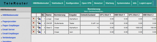
| Column | Description | |
|---|---|---|
| Name | Freely given name | |
| Standardization | Currently two types of normalization are supported, either “linear” or “texts” linear means that the value has to be converted by the PLC. In this case, the fields “PLC value1”, “HMI value1”, “PLC value2”, “HMI value2” are to be filled. Texts means you want the values from the PLC status texts assign. This may be e.g. The state of a multi-stage drive |
|
| Unit / State | For standardization “Text”, the states are listed here according to the following syntax: <Comparison> <Value>: <Text> For each state, enter a new line. <comparison> is optional. If <comparison> is not specified, this means checking equality. Example for drive: 0: OFF 1: Level1 2: Level2 For comparisons, you can also define the following states: A temperature is to be monitored. It is to output only a text, whether the value is in the limit or whether a border violation is present. The value is in the limit if it is between 20 and 30. This is as follows: \\> = 20: normal ⇐ 30: normal <20: too low \\> 30: too high \\> 60: much too high Enter the number here as the number Values that result from the conversion of the fields “PLC value1”, “HMI value 1”, “PLC value 2”, “HMI value 2” |
|
| Conversion | For the conversion of the numerical value of the PLC for the representation as a physical variable in the HMI module, an assignment of the PLC value and the HMI value is necessary. The displayed value is calculated as: w = m * x + t; w = the displayed value m = (HMI value2 - HMIWert1) / (PLC value2 - PLCWert1) t = (HMI value1 - m * PLC value1) x = the current PLC value for example, the PLC values 0 - 1000 should correspond to the display 0 to 100 (sh line 3 in the picture) |
|
| PLC-value 1 | PLC value, which corresponds to the HMI value of 1. (0) | |
| HMI-value 1 | HMI value corresponding to PLC value 1 (0) | |
| PLC-value 2 | PLC value corresponding to the HMI value 2 (1000) | |
| HMI-value 2 | HMI value corresponding to PLC value 2 (100) | |
Configure messages
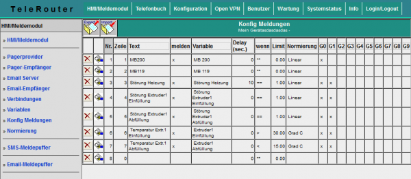
The actual messages are configured separately. The relationship between the variable, the standardization and the reporting group is made. What the actual message is. The sequence of the messages is made after entering the line number.
| Column | Usage |
|---|---|
| Row | Specify the order |
| Text | For free use and information to the user / plant operator |
| melden | Process the Row and forward it to group(s) |
| Variable | Here you assign one of the configured variables to the message. If no variable is assigned, only the text is displayed |
| Delay | The time in seconds for which a limit violation must be applied at least until it is reported. Thus, a measured value can be debounced. If the condition / comparison operation is used to determine a limit value violation or to determine the reporting conditions. Possible comparisons: == , >= , <= , <> and ** means no limit monitoring, that is, only display |
| G0 – G9 | The assignment to the individual detector groups, the respective message is assigned to a group of receivers |
To activate the message processing at all, basic settings must be made. Before you activate these settings, the mediations should be projected.
The importance of each Row:
| Row | Usage |
|---|---|
| Plant name | This text is sent to the receiver in the SMS header so that the sender can identify the sender |
| Send the broadcasting time | If “yes”, the transmission time is entered in the SMS header. Important: Set the time correctly |
| Enter the reporting time | If “yes”, the time at which the message occurred was entered for each message. This makes the SMS / Email text longer and more extensive. However, the time of occurrence can be reproduced for each message |
| Enable SMS Server | yes/no |
| Max. Number of send attempts SMS | This allows the number of maximum send attempts per SMS recipient to be set. Thus, it is possible to minimize excessive costs for unsuccessful SMS shipments in case of shipping problems |
| SMS sender identification for UCP | In the case of the UCP protocol, the sender's telephone number must be provided to the SMS server |
| Enable email service | yes/no |
| Max. Number of send attempts Email | This allows the number of maximum send attempts per e-mail recipient to be set |
SMS-Message buffer / Email-Message buffer

On the SMS Message Buffer page, the messages that are currently pending and not yet sent are displayed. The Column “Tx Trials” shows the number of attempts that have already been made to drop the SMS. This is greater than 0, e.g. Telephone line not available, busy or service settings (telephone number) are not correct. The largest number of attempts is reported to the PLC (see above).
Clicking on the symbol ![]() deletes all messages in the list. The messages are not sent!
deletes all messages in the list. The messages are not sent!
To testPurposeen remove the telephone cable, you can test the function of the system first without generating costs for sending SMS.
View messages

In the menu item View messages you can view the current status of the messages. All message states of the configured messages are displayed there. So also these, which can not generate SMS. As a result, a state can be obtained via the system without PLC programming software. The message window is updated every 3 seconds. Red fields indicate that there is a violation of the limit value.
S7-Firewall
Documentation for the Version 1.19
Introduction
S7 firewall is a scalable “PLC firewall”, which not only filters IP / MAC addresses, but also allows access to arbitrary data areas of the PLC to be restricted / defined. S7 firewall can be installed arbitrarily between PLC and operating / programming level. S7-firewall detects the installation direction automatically. Only configured connections are allowed.

Hardware version
Our S7 firewall is based on our TeleR4
Network settings

| Parameter | Possible setting | Purpose |
|---|---|---|
| Standard Gateway | fix (as defined), over DHCP | |
| 1. DNS | ||
| 2. DNS | ||
| 1-3. IP address with Netmask | IP address / Netmask | Netmask 0.0.0.0 automatically calculates netmask, depending on A, B, C-B network. e.g. 192.168.0.x → 255.255.255.0 10.x.x.x → 255.0.0.0 When using fixed IP addresses, at least the 1st IP address must be configured. Otherwise the device starts with the factory setting |
| DHCP | no | Do not use DHCP The remaining DHCP parameters are not used |
| Client | The network interface is called a DHCP client and obtains the IP address automatically from a DHCP server. The remaining DHCP parameters are not used | |
| Server | The network interface operates a DHCP server. The remaining DHCP parameters must be parameterized. | |
| Start-IP | Start-IP-Address | Start IP address when operating as a DHCP server |
| End-IP | End-IP-Address | End IP address when operating as a DHCP server |
| Subnet | Subnetaddress | Address of the subnet for assigning the IP addresses as a DHCP server |
| Domain | Free | Name of the domain when used as a DHCP server |
| Router-IP | IP-Address | Is the IP address, which is passed as a DHCP server as a gateway during operation |
The WAN / LAN port has shared IP addresses
Up to 3 different IP addresses and subnets can be configured.
The port can also be operated as a DHCP server or client.
The necessary data for the IP assignment is entered here.
For the operation as DHCP / server fixed assignments MAC-IP address can be fixed. (See “DHCP fixed addresses).
It also determines which services are available at the port (Web Config), Ping, SSH (for developers only)
Web-User
Here is the form for the input of the WEB-Interface users. Per user, different authorizations can be assigned.
In principle, only one user can make changes with “SU”. U1 - U5 is only allowed to operate the interface.
In the S7 firewall expansion modules, “U1” - “U5” have more precisely specified operating rights.

S7-Firewall-settings
The PLC firewall connections result from the combination of
HMI / PG station and PLC station

S7-Firewall operation

| Modi | Description |
|---|---|
| off | no active Firewall |
| S7-Firewall Router | WAN port and LAN ports have separate IP networks. All functions and purchased options of the TeleR <4> / sup> can be used |
| S7-Firewall Classic | WAN port and LAN ports are an IP network. Only IP address ranges entered in the WAN page are handled. for example IP WAN 192.168.2.15 IP LAN: 192.168.3.3 If a device with the IP 192.168.3.6 is connected, this is not treated until a 192.168.3.xxx address is entered in the WAN |
Enter the HMI / PG stations


| Parameter | Possible setting | Purpose |
|---|---|---|
| Nr. | Automatic | consecutive number |
| Name | Free from the user | station name |
| active | yes (x) | Connections to this station are handled by the firewall |
| no () | Connections to this station are not processed, i.e. they are blocked | |
| IP-Address | IP address of the HMI / PG device | Identification of the sender Input is essential |
| MAC-Address | MAC address of the HMI / PG device | Identifies the HMI / PG additionally via the MAC address. 00: 00: 00: 00: 00: 00 means that the MAC address is not checked. If the value is not equal to 0, the MAC address of the station must match the input |
| Connection channel | used channel of the connection: PG and OP channels are available in Simatic S7. This channel is used as an additional feature to identify the sender. Both PG and OP functions are possible on each of the two channels. |
|
| OP / HMI | HMI devices / WinCC etc. generally use OP channels. This channel is also the recommended one for HMI devices. | |
| PG | The Siemens PG software always uses the PG channel. Unfortunately, various software is in use on the market, which does not have the know-how to set this channel. This can be found out in the LOG file. Reasonable HMI software or the associated software driver provides the adjustability of this channel. | |
| PLC | The PLC channel corresponds to the “other” channel in the PLC | |
| PG | OP / HMI | run from the same computer PG and HMI (IP / MAC PG / HMI identical) remains only the PG / OP channel to identify the sender. | |
| PG | PLC | allow PG or PLC channel | |
| OP | PLC | allow OP or PLC channel | |
| PG | OP | PLC | allow PG or OP or PLC channel | |
| S7 over TSAP | S7 connection defined via TSAP | |
| RFC 1006 with TSAP | pure RFC 1006 Connection via TSAP. Note : no firewall rule applicable. All RFC 1006 traffic is passed through unfiltered! |
|
| local TSAP | String | only for S7 over TSAP and RFC 1006 with TSAP. Tipp: Enter a byte / hexadecimal value: e.g. HEX-TSAP 02.00 →% 02% 00 Note: even a space is considered as a character |
| remote TSAP | String | only for S7 over TSAP and RFC 1006 with TSAP. Enter a byte / hexadecimal value: e.g. HEX-TSAP 02.00 →% 02% 00 Note: even a space is considered as a character |
Input the PLC stations

| Parameter | Possible setting | Purpose |
|---|---|---|
| Nr. | automatic | consecutive number |
| Name | Free of the user | Name of the Station |
| active | yes (x) | Connections to this station are handled by the firewall |
| no() | Connections to this station are not processed, i. They are blocked | |
| IP-Address | IP address of the PLC station | Identification of the sender Entry required |
Enter the S7 firewall connections
The connections are made up of the combination HMI / PG station and PLC station. Each HMI / PLC station can be used several times. If the Mac or IP address is changed, this must only be changed centrally in the HMI / PG station or PLC station. Each connection is assigned a connection rule.
If “PG full function” is selected, this connection is a full access. In the future, this access can be divided more closely (Read / write defined blocks, PLC start / stop, reset, system data (read / write)).

| Parameter | Possible setting | Purpose |
|---|---|---|
| Nr. | automatic | consecutive number |
| Name | Free of the user | Connection name Also serves as a “link” to open and edit the rule script. |
| active | yes (x) | This connection is processed by the firewall |
| no () | This connection is not processed, i. It is blocked | |
| Allow PG Full Function | (x) | This connection is a PG connection and can carry out all functions |
| no () | This connection is a Restricted Connection. Only accesses to the shared function and data areas, as defined in the associated rule script, are permitted. |
The rule script
In the rule script, the data areas or possible accesses for the respective connection are defined. The script can be reached via the link of the name of the connection.

Syntax of the control script
| first Character | Function | Rest of the line |
|---|---|---|
| # | The line is a comment | free Text |
| Double slash | ||
| (No character, it equals operand / range) | The following section is only for reading (readonly) | Operand / Range see below |
| r: | ||
| w: | The following area is only for writing (writeonly) | |
| rw: | The following area is readable and writable (read / write) |
In a RuleRow, a single operand, or I can enter a range.
Example for entering individual operands: (source from Siemens STEP-S7 PG software)
| Allowed operand | Data type | Example(Mnemonik German) | Example (Mnemonik English) |
|---|---|---|---|
| Input I Output I Flag | BYTE | EB 1 I AB 10 I MB 10 | IB 1 I QB 10 I MB 10 |
| Input I Output I Flag | WORD | EW 1 I AW 10 I MW 10 | IW 1 I QW 10 I MW 10 |
| Input I Output I Flag | DWORD | ED 1 I AD 10 I MD 10 | ID 1 I QD 10 I MD 10 |
| Periphery (Input I Output) | BYTE | PB 0 I PEB 0 I PAB 1 | PB 0 I PIB 0 I PQB 1 |
| Periphery (Input I Output) | WORD | PW 0 I PEW 0 I PAW 1 | PW 0 I PIW 0 I PQW 1 |
| Periphery (Input I Output) | DWORD | PW 0 I PED 0 I PAD 1 | PD 0 I PID 0 I PQD 1 |
| Timer | TIMER | T 1 | T 1 |
| Counter | COUNTER | Z 1 | C 1 |
| Data block | BOOL | DB1.DBX 1.0 | DB1.DBX 1.0 |
| Data block | BYTE | DB1.DBB 1 | DB1.DBB 1 |
| Data block | WORD | DB1.DBW 1 | DB1.DBW 1 |
| Data block | DWORD | DB1.DBD 1 | DB1.DBD 1 |
Note: The entry of “DB0 …” is not allowed due to internal use.
Example for entering ranges, with number of units:
since Flag 60, 10 Byte: MB60, 10
since DB10, Data word 2, 5 words: DB10.DW2, 5
After the comma, the number of units required (depending on the address type, BOOL, BYTE, WORD, DWORD)
Example for entering ranges from “from” to ”:“
Flag Byte 70 bis Flag Byte 200: MB 70 – MB 200
Output A 10.2 bis Output 14.7: A 10.2 – A14.7
Just after start operands with, -, specify the end operand (end address). The end address is included!
Mointing
 On the back are four screw holes.
Mount the supplied DIN rail bracket so that the spring faces downwards.
On the back are four screw holes.
Mount the supplied DIN rail bracket so that the spring faces downwards.
Assembly:
First hook into the DIN rail and then push / pull the TeleR2 / TeleR4 into the holder.
Dismantling:
To disassemble, lift the TeleR2 / TeleR4 and tilt it slightly forward.
Technical Data
| port | Data |
|---|---|
| LAN/WAN | TeleR²: 1 x WAN + 1 x LAN Ethernet 10/100 Mbit TeleR4: 1 x WAN + 3 x LAN 10/100 Mbits Switch |
| Power supply | 10V - 30V DC |
| DIN/DOUT | Input Low: An input voltage of less than 5-6V is detected as a low signal. Input High: An input voltage greater than 5-6V is detected as a high signal. The maximum input voltage is 30V. The input current is limited to a maximum of 4mA. Output Low: The output is high-impedance. Output High: The operating voltage (10-30V) minus approx. 0.5V is switched to the outside. This can be loaded with a maximum of 180mA, then the current limiter starts and the voltage drops. |
| USB | 2.0 |
| Others | |
| Dimensions | 55mm x 70mm x 120mm (B xH x L) |
| Delivery | DIN Rail Mounting Gummifüße for operation as a desktop device Including IP-Address-Changer: Brings participants with the same IP-address into another common network |
| Case | Aluminum housing |
| Temperature range | -25°C - +75°C |
Power supply

| Pin Nr. | Short form | Designation | Direction |
|---|---|---|---|
| 1 | POW + | 10-30V DC voltage | Input |
| 2 | POW - | Ground | Input |
For the voltage supply of the device, either the supplied plug-in power supply or an on-site voltage supply of 10-30V / DC With min. 350mA current connected to the green 2-pin connector. The voltage poles are marked with colored wire end ferrules for the supplied plug-in power supply.
The PLUS pole with the color “red”, the MINUS pole with the color “blue”. Connect the PLUS pole to the upper screw terminal and the MINUS terminal to the lower (outer) screw terminal.
The “Power” LED is lit. After a short initialization phase, the “S1” LED is lit in steady light and the device is ready for operation.
Commercial data
| Item number | Designation | Additional text |
|---|---|---|
| 9374-PPPoE Customs tariff number: 85176200 | TeleR2 | 1 x WAN, 1 x LAN incl. DIN Rail Mounting 1 x DOUT, 1 x DIN incl. IP-Address-Changer origin: DE |
| 9374-4-PPPoE Customs tariff number: 85176200 | TeleR4 | 1 x WAN, 3 x LAN incl. DIN Rail Mounting 1 x DOUT, 1 x DIN incl. IP-Address-Changer origin: DE |
| 9374-S7-Firewall Customs tariff number: 85176200 | S7-Firewall | 1 x WAN, 3 x LAN incl. DIN Rail Mounting 1 x DOUT, 1 x DIN origin: DE |
| Options | ||
| 9374-O-CVPN | VPN-User Control | VPN-User via HTTP-command Enable / Disable |
| 9374-O-EMAIL | Configurable message system on WEB basis for sending messages and reports by e-mail | |
| 9374-O-NOTIFY | m2mNotify via CoDaBix | Configurable message system on WEB basis for sending messages via the CoDaBix to mobile apps |
| 9374-O-PN-ROUTER | ProfiNet-Router | Connect selected ProfiNet stations via modem / DSL / Internet with VPN - Remote maintenance Simatic S7 Profibus via Internet with VPN / Modem - Profibus telegrams Routing |
| 9374-O-S7FW | S7-Firewall | Scalable “PLC firewall” far beyond IP / MAC address filtering, complete or individual process data areas can be protected, even up to individual bits of the control |
| 9374-O-Userroute | Userroute | User-specific routing: For each individual user, specify which devices (IP addresses) and with which port may be accessed |
| Equipment | ||
| 9374-SW | 5 Port Industrial Switch | 10/100MBit DIN Rail Mounting 12-48V DC |
WAN/PPPoE: IP-Routing over PPPoE am WAN-Port
WAN/OVPN: routing only over OVPN on WAN-Port
WAN/PPPoE: IP-Routing over PPPoE am WAN-Port
WAN/OVPN: Routing only over OVPN to WAN-Port
WAN/PPPoE: IP routing via PPPoE on the WAN port
WAN/OVPN: only routing via OVPN on the WAN port
WAN/PPPoE: IP routing via PPPoE at the WAN port
WAN/OVPN: only routing via OVPN at the WAN port
WAN/OVPN: only routing over OVPN at the WAN port
WAN/OVPN: only routing over OVPN at the WAN port